Continuous Insulation for Mitigation of Thermal Bridges
by Jonathan McGaha | 1 March 2015 12:00 am

There are many benefits of adding a thermal break and continuous insulation
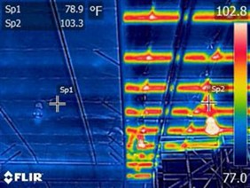
The infrared photograph in Figure 1 where red is 103.3 F and blue is 78.9 F clearly Illustrates the reality of thermal bridging that can occur with metal structures. There is no mystery concerning the reason for the temperature variation shown in the figure. Metal framing material of any type has a much greater thermal conductivity than the insulation commonly installed between the framing elements. The thermal conductivity of steel is around 300 Btu∙in./ft2∙h∙F in the temperature range of interest while common fibrous insulations have values of 0.25 to 0.3 in the same units. The area occupied by the metal framing members is smaller than the area occupied by insulation, but the enormous difference between thermal properties remains. The region affected by metal framing depends on the area of the flange, not just the thickness of the metal that creates the thermal bridge.
 |
|
| Figure 1: Photograph of ceiling below a metal roof assembly |
The impact of the thermal bridge can be illustrated using a few zone calculations based on equations in Chapter 26 in the “ASHRAE Handbook of Fundamentals” to show the breakdown between heat flow through the metal assembly and heat flow through the insulated region. Examples in the following table show that 37 to 42 percent of the heat flow is through the relatively small metal-zone areas for a roof-panel temperature of 110 F and an interior-air temperature of 70 F. The zone method takes heat flow through the metal structure to be in parallel with the heat flow through the insulated region, adds airfilm resistances, and any additional resistance such as continuous insulation (CI) to arrive at a U-factor for an assembly containing R-19 insulation.
The heat flow through the assembly is proportional to the U-factor (a 10 percent reduction in U results in a 10 percent reduction in heat flow). By and large, this is well known to heat-transfer specialists and well represented by insulation assembly requirements in ASHRAE Standard 90.1 and building code requirements for CI.
A solution to the thermal bridging has been identified. Add insulation (thermal break) to the region occupied by metal framing, add CI, or both. ASHRAE Standard 90.1 contains specifications for metal buildings that rely heavily on thermal breaks and CI to achieve low U-values that result in reduced utility cost. Practical considerations enter the discussion in the case of retrofits. CI can be added to either side of the assembly making this approach attractive for retrofit applications.
Table 1.
|
|||
| Assembly | Metal Region | Insulated Region | U-Factor |
|
6-inch purlin 48-inch OC with R-19 insulation, no thermal block. |
42% | 58% | 0.083 |
| Same as above with 60-inch OC purlins | 37% | 63% | 0.076 |
|
Same as above with R-2 added to the metal |
13% | 87% | 0.045 |
| Both regions with high-emittance white facer | 25% | 75% | 0.058 |
|
60-inch OC with 3 CI with high-emittance white facer |
18% | 82% | 0.051 |
| * R-values with units ft2∙h∙F/Btu |
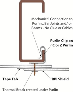
The diagram in Figure 2 shows a CI addition on the interior side of the roof assembly that has a thermal break region with twice the thermal resistance of the CI layer. The performance of the roof assembly is further enhanced if the CI which faces the conditioned space in this case has low-emittance with enhanced high air-film resistance. Aluminum foil or metalized aluminum films, for example, have emittances in the range 0.03 to 0.06. A U-factor calculation for the above system based on the 60-inch on-center (OC) assembly with high-emittance facer in Table 1 gives the result 0.076 and 0.045 when CI with low-emittance facer is used. This CI and low-emittance facer provides 41 percent reduction from the U-factor 0.076 shown in Table 1 for heat-flow down. This solution to the thermal bridge effect involves three factors: addition of thermal resistance in the low resistance metal-zone path, addition of CI with R-1, and a large increase in the air-film resistance below the roof/ceiling system.
Fi-Foil Co., Auburndale, Fla., developed the Clip-and-Pin component shown in Figure 2 to utilize a layer of reflective layer as CI. This type of CI has R-2 in the metal zone path and R-1 in the cavity path to achieve the third result shown in Table 1. The system encloses in some cases a reflective air space between the CI and
 |
|
| Figure 2: Clip for adding CI to the interior side of the assembly |
insulation that is draped over the roof purlins to provide R-value in addition to the CI. The RetroShield System can also be used to support fiberglass, rock wool or cotton batts. The system can provide CI below or inside the metal framing for roofs and walls, respectively with either an aluminum foil facer (low emittance) or a white facer (high emittance).
Bill Lippy is president and David Yarbrough is co-founder and vice president of research and development of Fi-Foil Co., Auburndale, Fla. To learn more, visit www.fifoil.com[1].
- www.fifoil.com: http://www.fifoil.com
Source URL: https://www.metalconstructionnews.com/articles/continuous-insulation-for-mitigation-of-thermal-bridges/