Path of Least Resistance
by Brooke Smith | 15 February 2024 7:00 am
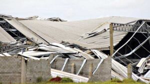 [1]Metal roofing can be the construction industry’s most durable roofing system by design. However, all things have certain weak links. If not properly designed, tested, and installed, roofs can fail in a windstorm. A big problem is the rules around “properly designed” keep changing, with the engineering standards that govern wind design, ASCE 7 Minimum Design Loads and Associated Criteria for Buildings and Other Structures.
Metal roofing is known for its durability, long-lasting performance, and reliability. The exceptional performance of metal roofing in high-wind conditions is due, in part, to its attachment methods and interlocking installation where roof panels are overlapped and attached to the structure of the building, reducing the ability of wind to disrupt the panels.
Standing seam metal roofing has a distinct advantage over other roof types—such as membrane and hot-applied asphaltic roofs—because it serves as a “structural” covering. That means, it can be engineered to withstand almost any force imposed by wind, transferring all environmental loads directly into the building structure. When so designed, some structural standing seam profiles can withstand extremely high forces, making metal the roof material of choice in high-wind regions.
Design wind speed and wind forces
Wind is a fluid—like water. Just as the speed of the flow of a stream or riverbed increases, resulting in “rapids” as its width narrows, wind acts in a similar fashion influenced by its surrounding terrain. Basic wind speeds vary throughout the U.S. The basic or “design” wind speed is determined by an area’s historically highest recorded three-second wind gust—measured 10 m (33 ft) above ground—which, in turn, is used to calculate the maximum overturning forces on a building and the uplift forces on its roof. The reason for measurement at a significant height is the ground presents frictional resistance to wind just as rocks, vegetation, debris, and twists and turns present frictional resistance within a stream or riverbed. So, measuring wind speed closer to the ground could be misleading.
Higher wind-prone areas are generally found in coastal communities due to open ocean water (no obstructions) and hurricane probabilities. Basic wind speeds may also be higher in some mountainous regions due to the funneling effects of the terrain. Large expanses of flat plains (no obstructions to wind) in some interior states may also experience higher design wind speeds. A building’s immediate surroundings also impact wind speeds. Valleys, hills, slopes, cliffsides, and large open-water lakes can increase wind effects by creating “wind tunnels” with funneling effects. Obstacles in the wind’s path, such as nearby buildings and heavily wooded areas, can also reduce wind effects on a building and its roof.
Wind speed (measured by km/h or mph) must be translated into units of force (pascals [Pa] or pounds per square foot [psf]) for design purposes in accordance with engineering standard ASCE 7. The resulting forces vary in different roof “zones” (areas of the roof). Figure 1 (page 26) represents a gable roof of less than seven degrees (1.5:12) or a single roof plane of steeper slope.
The “1” zone experiences the least force. Perimeter “2” and corner “3” zones experience higher forces than the central “1” zone of the roof area. On roofs with slopes of seven degrees or more, the zones adjacent to the ridge also experience higher forces. A relatively larger roof print as compared to a wall footprint, such as a large product distribution center, may result in a “11” roof zone with forces lower than the “1” zone. In addition, a building’s roof size, geometry, and height also impact the dimensional size of these zones as well as the severity of forces.
The walls of a building act as obstacles that collect and redirect the flow of large volumes of wind fluid around the building’s corners and over rooflines (Figure 2, page 26). For example, an 18-m (60-ft) tall building experiences stronger wind forces than a 9-m (30-ft) tall building with a similar footprint, even if both are in the same area with the same design wind speed. In short, the larger the wall areas are that collect and redirect wind, the more the forces of roof uplift are exaggerated. The windward wall experiences “positive” pressure, but as the fluid is redirected over the roof, “negative” pressure (vacuum) is experienced by the roof—especially at the eave area or gable, whichever faces windward. The negative pressure, or “pressure deficit,” is called “wind uplift” and is expressed in Pa or psf.
Wind uplift: a design engineering consideration for any roof
Proper roof design depends on the region’s basic wind speeds and how the aforementioned factors alter the wind forces. No matter where a building is located or what material it is constructed from, there are minimum standards of wind uplift forces its roof should withstand. As uplift forces increase, roofs must be more resistant to them. Metal roofing lends itself to high-wind areas because it can be engineered easily to withstand nearly any uplift force within the design stage.
The maximum wind uplift pressure for which a building must be designed is calculated based on formulae in ASCE 7, which is updated periodically. ASCE 7-22 is the latest ratified version, but it has not yet been adopted by any state or local jurisdiction. Currently, ASCE 7-16 is the most widely used, but some states still use earlier versions. The formulae and factors used to calculate minimum design loads in ASCE 7 evolve with each new version due to changing historical weather data. As a result, there are significant changes in design parameters from earlier versions of ASCE 7-05 to 7-10, then 7-16 and now 7-22, most of which mandate higher wind design pressures.
Testing standards for wind resistance
Metal roofing is designed with varying resistance to wind forces specific to a building, so materials, products, and roof designs/assemblies must be tested for all wind uplift pressures to prove and quantify their strength. Further, testing specific roof system assemblies is necessary to determine their various resistances to wind forces so the appropriate roof assembly can be used in building design and specification.
There are three well-recognized “wind test” methods, including Underwriters Laboratories (UL) 580, Factory Mutual (FM) 4471, and ASTM E1592. Technically speaking, none of the three relates directly to wind speeds, but the FM and ASTM procedures are structural capacity tests that relate to resulting forces. Any of these test standards may appear in design specifications.
UL 580: Tests for Uplift Resistance of Roof Assemblies
This test method is used to evaluate the wind uplift resistance of roofing assemblies when subject to undulating and static loads from above and/or below the specimen. The test evaluates the roof coverings and their attachment to spaced supports or decking. UL 580 is best used as a comparative test since it does not simulate specific wind speeds or forces. The physical size of the roof specimen is 3.05 x 3.05 m (10 x 10 ft), and all perimeter edges are fastened to the test frame. The test assembly is subject to increasing levels of static and oscillating pressures to achieve a Class rating (UL-15, 30, 60, or 90). UL 580 is an incremental pass/fail test for specific Classes and does not determine the exact ultimate resistance of the panel assembly. In addition, test assembly is built up of a specific substructure with specific clip/fastener spacings, and specific roof panels.
FM-4471: Approval Standard for Class 1 Panel Roofs/Roof Assemblies
This test standard includes the potential for flame-spread on the underside and exterior of the roof panel. It also measures the ability to resist simulated wind uplift force while maintaining adequate strength and durability. The roof uplift section of this standard tests all components necessary and specific to the installation of the roof panel assembly. This includes the potential for fire spread on the underside and exterior of the roof panel. It also measures the ability to resist simulated wind uplift force while maintaining adequate strength and durability. FM 4471 uses a 3.65 x 7.3 m (12 x 24 ft) section, which is larger than the specimen used in UL 580. The panels are subjected to increased wind pressure levels until the assembly fails. The ratings are stated as I-60, I-90, I-120, and so on, referring to static, uniform wind pressure in psf. (Note: The prefix “I” is often mistaken as a letter, but it is the Roman numeral for one, referring to the fire classification of the test.)
The most widely used test standard by the structural roof system manufacturing community today, ASTM E1592, Standard Test Method for Structural Performance of Sheet Metal Roof and Siding Systems by Uniform Static Air Pressure Difference, is performed by applying a constantly increasing pressure until failure, to determine the ultimate uplift load capacity. The test specimen is either 3.65 x 6.1 m (12 x 20 ft) with one end fastened to the test frame or 3.65 x 7.3 m (12 x 24 ft) with both ends fastened to the test frame. In either case, the sides of the test specimen are also fastened. This roof test procedure involves panels, clips, and interface of the two. ASTM E1592 quantifies the maximum structural capacity of the panel-clip assembly in psf.
The Metal Construction Association (MCA) has published a seven-part series white paper, Metal Roofing A to Z, in which Part 6 deals with wind effects.
Metal roof design and impact on wind resistance
A metal roof system is a “load chain” consisting of numerous factors and components: the “beam strength” of the panel under negative load; the clip that attaches it to the structure, including its design, material, and integration into the seam; the interface within dual component clips; and the method/strength of the fastening of the clip to the structure. When the weakest link fails, the chain is broken. Strengthening one link moves the failure mode to another link. The chain will still break at some point—albeit at a higher load—hence, the strength of the “chain” is improved.
Multiple links in the load chain yield myriad choices for improving the wind resistance of a roof system, all with various strength improvements and cost considerations. The key is to strengthen the weakest links while obtaining “the best bang for the buck.”
One option is to use more material to increase wind uplift performance, either by increasing panel material thickness or narrowing the panel covering width to create more seams (points of attachment). Another alternative is to decrease the panel spans by adding more purlins; hence, decreasing the clip spacing (more points of attachment). Using more material in clip design (heavier gauge, longer length) is still another option. All these alternatives can be used alone or in combination to address multiple weak links in the load chain, but all involve significant costs. As a practical matter, these improvements can be implemented in new construction, but none can be performed affordably on an existing roof.
Finally, uplift performance can be significantly increased on standing seam roofs with the use of wind clamps (or external seam clamps as termed by one insurance carrier) for a significantly lower cost compared to other options. Wind clamps can be used for new or existing construction. Placed over the roof’s seams at designated intervals, these clamps measurably increase the roof’s wind resistance capacity, preventing multiple modes of failure, including seam separation and clip disengagement (when used at roof clip locations). These are the two most common “weak links” in the chain.
As outlined, the growing adoption of ASCE 7-16 has resulted in increased uplift requirements for many sites, buildings, roofs, and/or roof zones across the country. ASCE 7-22 introduces even greater requirements. Preserving insurability or seeking lower premiums makes bringing buildings up to code necessary. Installing wind clamps is an endorsed and even documented method for bringing standing seam metal roofs up to code. One insurer has even published prescriptive guidance for these clamps in their Property Loss Data Sheet 1-31.
Key takeaways
With appropriate design and testing, metal roofing affords greater durability than other roof types and is particularly critical for use in high-wind areas. According to a summary by the staff of Monroe County, Fla., post-Hurricane Irma inspections found that “metal roofs fared far better than those roofs covered by asphalt shingles,” and in recent years, county officials even proposed an ordinance to require all new or replacement roofs to be metal.* That’s a true testament to the sustainability and durability of metal roofing, particularly in high-wind-prone areas. At pennies per square foot, installing wind clamps is not only the most cost-effective method to strengthen a standing seam metal roof, but also the simplest and least intrusive, improving wind resistance by as much as two and three times in many cases. Increasing the durability of a metal roof is prudent—whether it is for code compliance, insurability, or just plain peace of mind.
Note
* See “Next roof on Florida Keys homes could be metal by mandate” by Kevin Wadlow in FL Keys News. flkeysnews.com/news/local/article183940626.html
Rob Haddock, CEO and founder of S-5!, is a former contractor, award-winning roof forensics expert, author, lecturer, and building envelope scientist who has worked in various aspects of metal roofing for five decades. S-5! first introduced and commercialized special wind clamp technology in 1995—more than 15 years before the introduction of the term “external seam clamps.”
- [Image]: https://www.metalconstructionnews.com/wp-content/uploads/2024/02/Wind-Uplifting-or-NOT-MRIL2081091621-1.pptx-1.jpg
Source URL: https://www.metalconstructionnews.com/articles/features/path-of-least-resistance/