Excellent flexibility, resistance to core shear and adhesion properties
Continuous line, factory-foamed insulated metal panels (IMPs) utilize Class 1 semi-rigid polyurethane foam cores with excellent flexibility, resistance to core shear and adhesion properties. When panels are mechanically fastened to the perpendicular supports, they rigidize the assembly and rely on the thermal expansion coefficients of the foam core and exterior steel facing as a unitized composite to withstand movement without structurally compromising the components.
The thermal expansion coefficient in steel is also higher than that of the foam core. Therefore, as the exterior and interior facings are exposed to temperature differentials at the same time
(also termed “delta”), the panel composite may bow out of plane with the warmer face becoming convex due to the expansion of the metal. On cooler and freezer buildings, thermal bowing can be even more exaggerated because of the increased temperature differential.
 |
| Figure 1 (Image courtesy of All Weather Insulated Panels) |
Most IMP manufacturers incorporate software programs that have been developed based on the physical characteristics of the product components and industry engineering standards. The principles and design of sandwich panels developed in both Europe and North America have proved to be extremely valuable in predetermining the performance of IMP wall and roof assemblies.
Analyses include an evaluation of the following design parameters: panel type, core thickness, steel thickness, panel length, panel color, building orientation, span between structural supports, temperature differential, fastening patterns, wind loads and panel end use. Unchecked, the long-term results of excessive thermal bowing will induce aesthetic failure through thermal rippling and potential delamination resulting in blisters and creases as the panels look for a way to relieve stress. Figure 1 shows an exaggerated image of thermal bow on an insulated metal panel.
Framed Openings
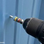
IMP exterior face stress potential is exacerbated in corners, doors, windows or any openings where panels are further rigidized with extra framing. Field interior relief cuts are recommended at the panels that are cut to fit any framed openings. The interior cut is made on the panel adjacent to the header framing (or the closest girt, if not on the same elevation.) This cut should not be farther than 2 inches from the girt if a typical circular saw is used, and the cuts should not be visible from the floor level since the flange of the girt will cover the cut. White silicone sealant can be applied over the cut area if desired.
For walls with multiple overhead doors spaced relatively close to one another, a continuous stack joint at the framed opening header elevation is recommended. If single-length panels are absolutely needed, an exterior relief cut will be required to relieve the stress caused by over-rigidization. This cut can be made and trimmed out after panels are notched and installed.
Supporting Steel
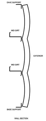
For quality panel installation, it is imperative that the supporting steel is property aligned before the installation of wall panels. The maximum deviation of steel alignment should be limited to 0 + 3/16-inch from the control with a 1/8-inch maximum change in deviation for any member of any 10 feet, 0 inches run of panel. Figure 2 illustrates an extreme condition where girts are out of plumb, which can result in additional stress in the panel.
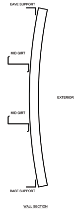 |
| Figure 2 (Image courtesy of All Weather Insulated Panels) |
Furthermore, secondary framing shall run perpendicular to the panel length for proper fastening. When framing runs along the length of panel, the panel is restricted from any thermal bow and can result in panel failure. As such, panels shall not be installed to columns when used with “flush set” girts. If the panel joinery falls on a column, flange clips with expansion fasteners shall be used to fasten the panels onto each adjacent girt. The same procedure is applicable to corner conditions as well.
Thermal Blisters
Thermal blisters are round or oblong “bubbles” in the steel facing that can form from a combination of face delamination and the subsequent release of blowing agent gases from the foam core substrate. After migrating from the foam core into the space behind the blister, the blowing agent can expand under extreme temperatures and create a bubble on the panel face. Although current technologies have vastly improved foam processing resulting in superior tensile adhesion strength, thermal blisters can still appear occasionally, especially where undue face stress is present.
In most applications, insulated metal panels are not used as structural supports and only need to perform as a building cladding subjected to standard design loads. Therefore, thermal blisters will not measurably compromise the panel strength, particularly if they are mechanically fastened through both facings into the supporting structure. Thermal blisters can be relieved by drilling a maximum 1/16-inch hole through the metal skin at the bottom of the blister to release the expanded blowing agent. It is imperative that the cause of the blistering be determined and corrections made to mitigate future blistering prior to making repairs. Detailed procedures can be obtained from the manufacturer.
Brian Ng is technical director at All Weather Insulated Panels, Vacaville, Calif. For more information, go to www.awipanels.com.