The primary frames used in metal building systems (MBS) provide a skeleton that help the structure survive extreme weather events. There are some pitfalls in specifying and building these vital structural elements.
Be aware of a pitfall associated with tapered-beam projects and ask the right questions

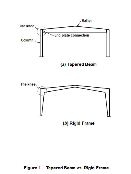
The common types of primary frames are well familiar to the readers of Metal Construction News. They include tapered beam (Figure 1a), single- and multiple-span moment-resisting (rigid) frames, and single-span and continuous trusses. There are also lean-to buildings, which rely on another structure for support.
Perhaps the most misunderstood type of primary frame is the tapered beam, particularly the connection between the horizontal part (the rafter) and the column. In a rigid-frame system, this connection, called the knee, is capable of resisting the design bending moment. Put simply, the column and the rafter are rigidly interconnected. The knee is often the most critically stressed part of the frame. This is why MBS rigid frames often have tapered profiles, with the knees being the deepest parts of the frames (Figure 1b).
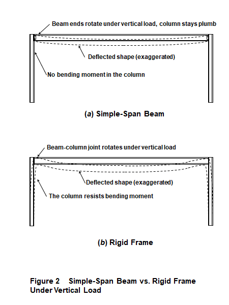
By contrast, a typical simple-span steel beam is attached to its supports with so-called simple connections, where the beam transmits a negligible bending moment to the column. The beam ends can slightly rotate under load (Figure 2a).
In the tapered-beam system, the knee consists of bolted end plates covering the entire depth of the rafter or extending slightly beyond its flanges. The American Institute of Steel Construction (AISC) considers it a moment-resisting connection, and most reputable MBS manufacturers market such products as tapered-beam rigid frames.
However, some suppliers claim that the connection at the tapered-beam knee is a semi-rigid one. I have called it a “smart connection” (no compliment here!), which supposedly knows what kind of load acts on the frame and behaves accordingly. Under gravity loading (snow or roof live load), the connection is supposed to be a simple one as described above. But under lateral (wind or seismic) loading, the connection behaves as a moment-resisting one.
To be sure, there are true semi-rigid, aka partially restrained steel connections, but they have a different design, such as two flexible angles placed below and above the ends of the rafter. By contrast, the full-depth end-plate connection is not semi-rigid; it is moment-resisting.
Why would somebody decide to take a chance with this unrealistic design assumption? Pretending that the rafter in a tapered beam acts as a simply supported beam under gravity loading allows the designer to make the column lighter. When the bending moment at the top of the column is neglected (Figure 2a), the column uses less steel than a properly designed rigid-frame column (Figure 2b). Another supposed benefit would be the absence of the horizontal reactions on the foundation under gravity loading, making the foundations less expensive.
Unfortunately, making unrealistic design assumptions does not change the actual behavior of the frame. In real life, the end-plate connection does not know about the designer’s “smart” computer modeling. The column in the tapered-beam frame designed this way, and the foundation under it will behave as actually constructed, not as the designer wanted, making both the column and the foundation under-designed.
With these “smart connections,” ignorance is no bliss.
Why would this technical discussion be of interest to metal building contractors? Because a deficient structure opens both the designer and the builder to potential liability in case of a structural failure. Contractors should be aware of the risks before getting involved with tapered-beam projects and should ask the right questions before signing the contract.
Making renovations to existing MBS buildings with tapered-beam frames might be even more problematic. The “smart connection” design was quite prevalent in the past, probably more so than today. Making alterations to such structures—especially weakening them in some fashion—might in some situations make the designers and builders responsible for the resulting structure and its design deficiencies.
Some additional pitfalls in specifying and building the primary frames in MBS will be discussed in future columns.
Alexander Newman, PE, is a Boston-based forensic structural consultant with more than 40 years of design and forensic experience. He specializes in controversies, claims and litigation involving metal building systems, and is the author of “Metal Building Systems: Design and Specifications,” Third edition. (McGraw-Hill, 2015) and two other authoritative reference books. Contact him at newmanauthor.com.