This month’s column continues the discussion of avoiding pitfalls in working with primary frames used in metal building systems (MBS). The previous column mentioned several common types of primary frames, which also include lean-to systems. As the name suggests, a lean-to frame relies on another structure for one of its supports.
Lean-tos are economical ways to add space but require special attention to framing

Most commonly, lean-tos are used as extensions (wings) of primary gable frames. The wings can accommodate storage areas, equipment rooms and any number of uses that do not require the headroom available within the main space. Common spans of lean-to rafters, which are often tapered downward, are between 15 and 30 feet (Figure 1).
The advantages of lean-tos are obvious. Additional space can be gained relatively inexpensively as long as the diminished headroom within the wing is acceptable. The roof line can seamlessly continue into the lean-to, if desired. Straight, rather than tapered, columns can be used.

But now the complications start. In typical MBS construction, the exterior primary frame columns support wall girts, typically spaced between 6 and 8 feet on-center. While the columns support the girts, the girts strengthen the columns. How so?
In structural design, an unbraced MBS frame column has a much smaller structural capacity in the direction perpendicular to the frame span—the appropriately named “weak direction”—than in the direction of the span. For an interior column, the much smaller capacity in the weak direction controls the amount of vertical load the column can safely carry.
An exterior column, however, benefits from the girts framing into it, because they laterally brace the column. Instead of using the full height of the columns as their unbraced length, the exterior frame columns are considered laterally braced at each girt line. This allows the columns to support much higher gravity loading and makes the overall primary framing more economical.
But what about the middle column in Figure 1, which supports the lean-to? There are no wall girts at that location, and the column is laterally unbraced for its full height. In new construction, this simply means that this column must be stronger than the corresponding exterior column braced by girts. This minor trade-off of using lean-tos in new construction can be readily incorporated into the frame design at little added cost.
However, pitfalls appear when the unwary designers and contractors use the lean-to system for additions to the buildings where both exterior columns carry wall girts. In this case, wall siding and girts are typically removed at the interface to integrate the lean-to area into the main space.
With the girts gone, the column at the interface becomes unbraced—and greatly weakened. Not only that, but the weakened column now supports an additional vertical loading from the lean-to. Without strengthening, the column could become vulnerable to failure, which might lead to building collapse. Also, the foundation under that column would receive the same added loading from the lean-to and could also become vulnerable to overload and failure.
This is one notable example of an addition weakening the original structure. Unfortunately, using lean-tos for additions, without any engineering analysis of the original framing, is rather common. This is dangerous territory for everyone involved in the project.
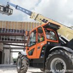
When lean-to additions are desired, the existing frame should be strengthened, particularly the column supporting the lean-to. The foundation under it should also be underpinned or strengthened by other means (Figure 2).

But isn’t it possible to remove the wall materials at the interface and keep the girts for bracing, avoiding the column strengthening? Not really, as girts themselves must be braced by the siding to be able to brace the columns. If the siding is gone, so is much of the bracing capacity of the girts. Plus, foundation strengthening would still be needed.
Instead of using a tied-in lean-to, a simpler design option is to build a separate addition with rigid frames next to the existing building (Figure 3). The size of the gap between the two buildings is determined by structural analysis. The existing girts and siding remain in place, with some minor reframing needed to provide for the new doorways connecting the two separate areas.

Additional pitfalls in specifying and building primary frames in MBS will be discussed in future columns.
Alexander Newman, PE, is a Boston-based forensic structural consultant with more than 40 years of design and forensic experience. He specializes in controversies, claims and litigation involving metal building systems, and is the author of “Metal Building Systems: Design and Specifications,” Third edition (McGraw-Hill, 2015), and two other authoritative reference books. Contact him at newmanauthor.com.