
Metal building construction has a long history of providing safe and cost-effective buildings such as churches, breweries, offices, manufacturing facilities, and warehouses. As the relevant building codes change over time, so does the way metal buildings are designed to meet those changes. The Metal Building Manufacturers Association (MBMA)—in collaboration with Jensen Hughes—has worked diligently over the years to develop new fire protection designs to meet these new code requirements. Following are the details MBMA developed for a head-of-wall continuity joint system between a fire barrier and an unrated roof assembly.
In 2012, the International Building Code (IBC) introduced a provision, Section 707.9, that required “[t]he voids created at the intersection of fire barriers and a non-fire-resistance-rated roof assembly shall be filled.”1 This same requirement has been maintained through to the 2021 edition of the IBC. The intent of this new language was to establish a means of slowing the passage of hot gases and flames from one side of the fire barrier to the other through the void created between the head of the wall and the unrated roof. Up through the current 2021 edition of the IBC, Section 707.9 requires the void infill to slow the passage of flames and for hot gases to be securely installed and not become dislodged or loose, but it did not require any specific fire test standard or any rating for the assembly that fills this void.
Unrated roof assemblies in metal buildings, which are common in one-story Type II-B construction, are unique because the typical roof glass fiber insulation material is draped from the structural purlins below the metal roof deck panels. In contrast to fire-resistance-rated joints that occur within or between fire-resistance-rated wall or floor assemblies, the interface between a fire-resistance-rated barrier and such an unrated roof assembly has been referred to as a “continuity joint system” by UL or a “void” by the IBC.
The MBMA has sponsored fire tests of various head-of-wall continuity joint systems in accordance with ASTM E2837, Standard Test Method for Determining the Fire Resistance of Continuity Head-of-Wall Joint Systems Installed Between Rated Wall Assemblies and Nonrated Horizontal Assemblies2—as well as engineering studies—that have resulted in the following UL Design Listings: CJ-D-0005, CJ-D-0006, CJ-D-0007, CJ-D-0029, CJ-D-0030, and CJ-D-0031. This group of assemblies represents three possible purlin-to-wall alignments (purlin inside wall, purlin perpendicular to wall, and purlin parallel to wall) and two roof insulation configurations (compressed and cavity filled). A full description of these head-of-wall continuity joint systems, fire-resistance-rated head-of-wall joint system UL Design Listings, and other fire-resistance-rated commentary specific to metal buildings can be found in the MBMA Fire Resistance Design Guide for Metal Building Systems.3
New continuity joint system
Due to the evolving and more demanding energy codes, a new head-of-wall continuity joint system with unrated roofs was needed to avoid the compression or interruption of more or thicker layers of roof insulation that would reduce the effectiveness of the thermal and vapor barrier performance at the wall. In response, MBMA developed and fire-tested a new head-of-wall continuity joint system that accommodates a fully insulated roof purlin cavity without the need to adjust, compress, or interrupt the roof insulation. Not only is this head-of-wall continuity joint system applicable to new construction, but it may also be utilized within existing construction projects without compromising or modifying the continuity of the existing roof insulation.
| 1A – Min. 16 ga steel U-shaped deflection channel | 2B – Purlin lateral bracing (not shown) |
| 1B – Fire barrier steel stud framing | 2C – Faced glass fiber insulation |
| 1C – Fire barrier gypsum wallboard | 2C1 – Unfaced glass fiber insulation |
| 1D – 15.87-mm (0.62-in.) Type X gypsum wallboard spacer block | 2D – Min. 24 ga coated steel roof deck panel |
| 1E – 12.7-mm (0.5-in.) min. Type X gypsum wallboard rip strip | 2E – Roof deck fasteners |
| 1F – Min. 20 ga, 66.67-mm (2.62-in.) wide, 22.22-mm (0.87-in.) deep galvanized steel hat channel | 3 – Intumescent fire caulk |
| 1G – 15.87-mm (0.62-in.) Type X gypsum wallboard wings | 4 – Unfaced mineral wool insulation min. 64 kg/m3 (4 pcf), min. 50 percent compression |
| 2A – Min. 254-mm (10-in.) deep 16 ga steel purlin |
| 1A – Min. 16 ga steel U-shaped deflection channel | 2B – Purlin lateral bracing (not shown) |
| 1B – Fire barrier steel stud framing | 2C – Faced glass fiber insulation |
| 1C – Fire barrier gypsum wallboard | 2C1 – Unfaced glass fiber insulation |
| 1D – 15.87 mm (0.62-in.) Type X gypsum wallboard spacer block | 2D – Min. 24 ga coated steel roof deck panel |
| 1E – 12.7-mm (0.5-in.) min. Type X gypsum wallboard rip strip | 2E – Roof deck fasteners |
| 1F – Min. 20 ga, 66.67-mm (2.62-in.) wide, 22.22-mm (0.87-in.) deep galvanized steel hat channel |
3 – Intumescent fire caulk |
| 1G – 15.87 mm (0.62-in.) Type X gypsum wallboard wings | 4 – Unfaced mineral wool insulation min. 64 kg/m3 (4 pcf), min. 50 percent compression |
| 2A – Min. 254-mm (10-in.) deep 16 ga steel purlin | 5 – Min. 20 ga, steel strap width equal to width of wall; secured to 1F with self-drilling screws |
| 1A – Min. 16 ga steel U-shaped deflection channel | 2A – Min. 254-mm (10-in.) deep 16 ga steel purlin |
| 1B – Fire barrier steel stud framing | 2B – Purlin lateral bracing (not shown) |
| 1C – Fire barrier gypsum wallboard | 2C – Faced glass fiber insulation |
| 1D – 15.87 mm (0.62-in.) Type X gypsum wallboard spacer block | 2C1 – Unfaced glass fiber insulation |
| 1E – 12.7-mm (0.5-in.) min. Type X gypsum wallboard rip strip | 2D – Min. 24 ga coated steel roof deck panel |
| 1F – Min. 25 ga, 66.67-mm (2.62-in.) wide, 22.22-mm (0.87-in.) deep galvanized steel hat channel | 2E – Roof deck fasteners |
| 1G – 15.87 mm (0.62-in.) Type X gypsum wallboard wings | 3 – Intumescent fire caulk |
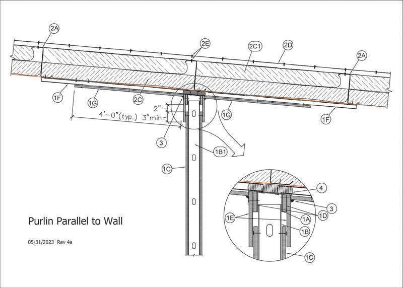
The overall design for this new continuity joint system can be described as a hybrid combination of a partial protective gypsum wallboard ceiling membrane in combination with the steel deflection channel features of the existing MBMA CJ-D UL Designs. All features of this new continuity joint system remain below the bottom flange of the purlins, the secondary roof framing members. Steel hat channels secured to the bottom flange of the purlins support the 1.21-m (4-ft) wide, 15.87-mm (0.62-in.)thick Type X gypsum wallboard ceiling membrane “wings” on both sides of the wall. The steel deflection channel (track) at the top of the wall is also secured to the hat channels, except when the wall is oriented perpendicular to the wall. In that orientation, the deflection channel is fastened directly to the bottom flange of the purlins. This new continuity joint system can be installed with the fire barrier parallel and aligned with the purlin (Figure 1), parallel and offset from the purlin (Figure 2), or perpendicular to the purlin (Figure 3).
The fire barrier parallel and aligned with the purlin (Figure 1) and parallel and offset from the purlin (Figure 2) conditions both have the top of the wall terminating at the underside of the steel hat channels. This results in the gypsum wallboard membranes also terminating at the underside of the hat channels. To ensure the continuity of the head-of-wall joint is maintained, the gap between the wall top track and faced glass fiber insulation must be filled. This void shall be filled with unfaced mineral wool insulation—nominally 50.8-mm (2-in.) thick, min. 64 kg/m3 (4 pcf)—that has a minimum compression of 50 percent.
For the case of the fire barrier parallel and aligned with the purlin (Figure 1), the mineral wool is compressed between the wall top track and the purlin. The mineral wool insulation shall be installed such that it is underneath the steel hat channels and within the steel hat channel profile—completely filling the void between the purlin and wall top track.
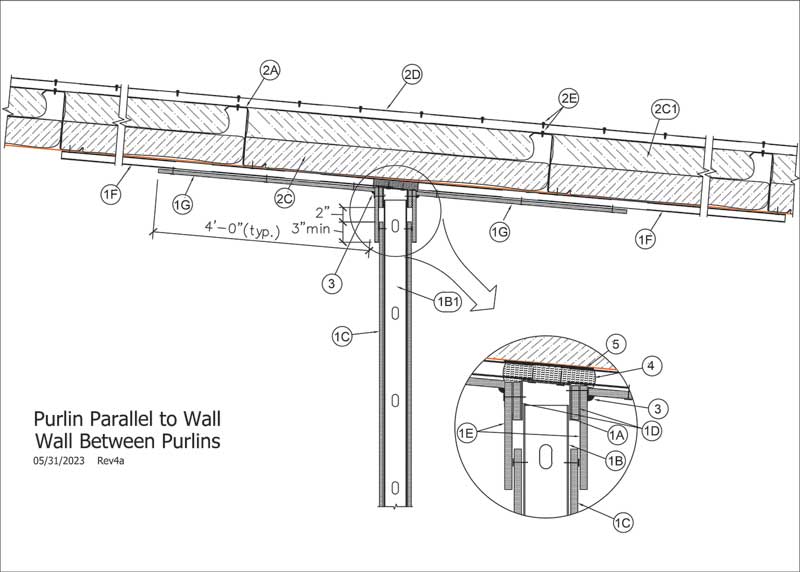
In the case of the fire barrier parallel and offset from the purlin (Figure 2), the purlin may not be utilized to provide the required support to compress the mineral wool insulation. Instead of the purlin, a min.
20 ga, steel strap with a width equal to width of wall will provide the mineral wool insulation support. The steel strap is installed between the faced glass fiber insulation and the top of the hat channel for the entire length of the fire barrier. The steel strap is secured to each steel hat channel from below with two self-tapping screws through the hat channel into the steel strap per hat channel. Once the steel strap is installed, the compressed mineral wool can be installed within the joint as described above. This steel strap method ensures the mineral wool insulation is adequately supported and does not compress the faced glass fiber insulation.
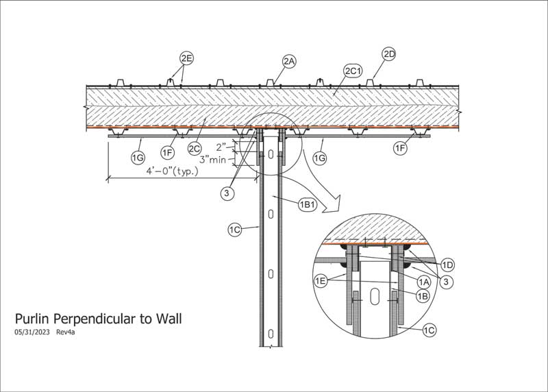
The fire barrier perpendicular to the purlin (Figure 3) has the top of the wall terminating at the underside of the purlin. In this configuration, the gypsum wallboard membranes can extend all the way up to the underside of the faced glass fiber insulation. Thus, the additional mineral wool insulation between the top of the wall and the purlin is not required to maintain continuity of the head-of-wall joint.
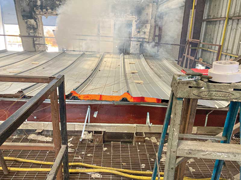
This new joint system was tested at Intertek Testing Services NA, Inc. in accordance with the ASTM E2837 standard. The tested one-hour fire-resistance-rated wall assembly was positioned during the test perpendicular to the roof purlins (worst-case orientation) and fully insulated roof cavity, as shown in Figure 3. The results of this testing showed the unrated roof assembly would fail first and provide venting of flames or hot gasses from the building before any failure of the wall or its continuity joint system (Figures 4 and 5). In other words, the unrated roof was demonstrated to be the proverbial “weakest link” of this intersection, as expected, thus satisfying the ASTM E2837 acceptance criteria. As previously stated, 2021 IBC Section 707.9 does not require the continuity joint system to be tested or have an hourly rating. Thus, compliance with the intent of this section of the code can be demonstrated via the “Alternative materials, design and methods of construction and equipment” code provisions found in IBC Section 104.11 based on this test.
IBC Section 715.8 of the 2021 edition establishes a maximum limit of 0.00775 m3/s m (5 cf per minute per linear foot) smoke (air) flow leakage rate through fire-resistance-rated joints at an air-pressure differential of 74.7 Pa (0.30 in.) of water for both ambient and elevated temperatures according to the ANSI/UL 2079, Tests for Fire Resistance of Building Joint Systems,4 standard. This air leakage, or L-rating, is an optional test in the ANSI/UL 2079 standard, which is determined at ambient and 204.44 C (400 F) air temperature. Since this smoke control requirement may also be checked for wall continuity joint systems at unrated roofs, the MBMA commissioned Intertek to include standard L-rating testing for this new joint system. The reported L-ratings, as follows, were less than the IBC maximum limit: 0.00011 m3/s m (0.07 cf per minute per linear foot) at ambient and 0.00563 m3/s m (3.63 cf per minute per linear foot) at 204.44 C (400 F).
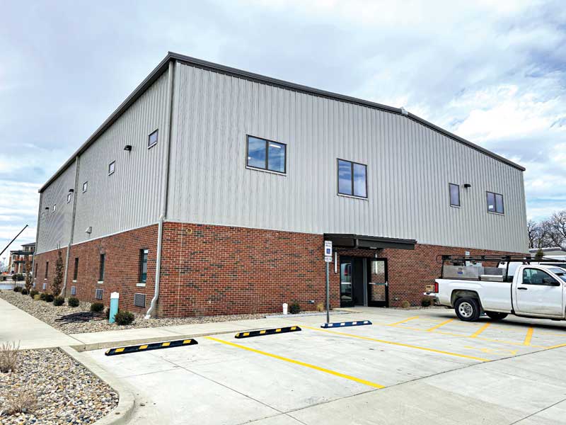
Example application
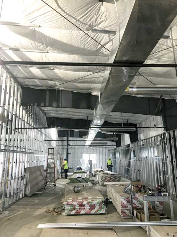
Jensen Hughes has previously written an engineering judgment for the use of this new continuity joint system in a Department of Corrections dormitory (Figure 6). As part of the project, multiple sleeping areas on the same floor were required to be separated by a one-hour, non-load-bearing fire-resistance-rated wall assembly. The top of the rated wall assemblies terminated at the underside of an unrated and fully insulated metal roof assembly supported by steel Z-purlins spaced at 1.52 m (5 ft) on center (Figure 7). Jensen Hughes was able to demonstrate via Section 104.11 of the IBC that the continuity joint system developed by the MBMA, as described here, met the intent of the code regarding Section 707.9 based on the fire testing conducted on the continuity joint system.
Conclusion
The MBMA has successfully developed a new head-of-wall continuity joint system with an unrated roof based on fire testing completed at Intertek. The joint’s efficiency and multiple benefits were summarized above. While the joint assembly is not listed as rated construction (because the unrated roof failed well before a one-hour fire exposure), the test vividly demonstrated the joint and wall provide adequate fire protection until such an occurrence consistent with the intent of IBC Section 707.9.
Daniel A. Martin, PE, CFEI, CVFI, is a fire protection engineer at Jensen Hughes Inc. He has eight years of experience at Jensen Hughes related to building code consulting, fire testing, passive fire protection engineering, code development, and fire investigation. Martin specializes in fire performance and flame spread analysis of building construction materials and assemblies by performing engineering evaluations and as a fire test consultant during qualification testing. He is also a member of numerous National Fire Protection Association (NFPA) and ASTM committees and participates in the International Code Council (ICC) code development process.
Vincent E. Sagan, PE, F.ASCE, is senior staff engineer with the Metal Building Manufacturers Association (MBMA). He serves as the project director for the second edition of the MBMA Fire Resistance Design Guide for Metal Building Systems and manages fire protection projects, including the development of fire resistance-rated designs, for the association. He represents the MBMA on the American Iron and Steel Institute (AISI) Committee on Specifications for the Design of Cold-Formed Steel Structural Members and several ASCE 7 subcommittees.
To help promote the expanded use and applications of this new continuity joint system, the MBMA will provide the Intertek test report for this joint system upon request and when needed to justify its approval by the authority having jurisdiction. Email mbma@mbma.com.
Notes
1 2012 International Building Code, International Code Council, Inc., Country Club Hills, Ill., October 2011.
2 ASTM E2837, Standard Test Method for Determining the Fire Resistance of Continuity Head-of-Wall Joint Systems Installed between Rated Wall Assemblies and Nonrated Horizontal Assemblies, ASTM International, West Conshohocken, Pa.
3 Fire Resistance Design Guide for Metal Building Systems, Metal Building Manufacturers Association, Cleveland, Ohio, 2010.
4 UL 2079, Test for Fire Resistance of Building Joint Systems, 2015 Edition, UL LLC, Northbrook, Ill.